The objective of Lab 6 is to develop a PID controller so that the robot mantains a certain angle, defined as a SetPoint.
Prelab
There is no prelab for this lab. However, as a reference, I will use the same debugging system as explained in Lab 5. In this lab no extrapolation is needed. In some instances, that argument will be useless. In others, I will use that first argument to test the maximum rotational speed that the IMU can read, as explained later. The SetPoint, Kp, Ki and Kd are still set the same way as the previous lab.
Tasks
1. Input Signal: Gyroscope Reading
The purpose of this lab is to maintain a certain orientation of the robot. To measure the orientation, we are going to use the gyroscope inside the IMU. As shown in Lab 4, the IMU is flat in the robot, so by reading the Z measure from the IMU we can obtain the yaw. However, the IMU measures angular speed, so we need to integrate it to obtain degrees. Additionally, I will use the function remainder() to limit the angles to ±180º. Note that the units of dt are milliseconds (as I use millis()); but we need to use seconds when obtaining the yaw (angular speed is in dps).
12345678
//Read angular speedori.ang_speed = myICM.gyrZ(); //Obtain dt, yaw and limit angles to +-180 degreesori.dt = ori.curr_time - ori.last_time;ori.raw_yaw = ori.yaw + ori.ang_speed*ori.dt/1000;ori.yaw = remainder(ori.raw_yaw, 360);
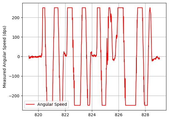
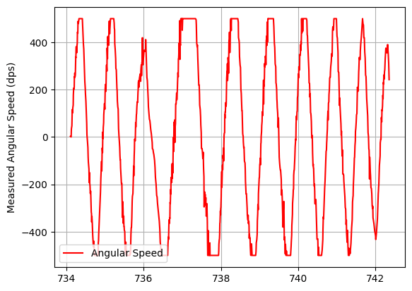
Initially, the angle measurement is not completely accurate. This is because the gyroscope has a limit on the maximum angular speed it can read. We can change it with setFullScale() and the variable myFSS.g. Its value will be dps followed by a number, which corresponds to the limit on the maximum angular speed. By default, it is set in dps250.
123
myFSS.g = dps1000; // (ICM_20948_GYRO_CONFIG_1_FS_SEL_e). Can be dps250, dps500, dps1000, or dps2000 myICM.setFullScale(ICM_20948_Internal_Gyr, myFSS);
I will run a test with very fast angular speeds, and different values of myFSS.g (changed with Bluetooth). We can see that the speed is capped in both dps250 and dps500; but it doesn’t get past 1000dps, which will be my maximum angular speed.
| Limit at 250dps | Limit at 500dps |
 |  |
| Limit at 1000dps | Limit at 2000dps |
 |  |
Additionally, when the robot is still, the IMU still measures some angular speed, leading to some drift in the yaw. However, this value is less than 1º, so we don’t need to worry too much about it. Also, small errors are considered 0, so this deviations don’t affect the controller.

Last, there’s no need for extrapolation. From Lab 2, we determined that the IMU sampling rate was around 4ms. In Lab 5, the sampling rate with extrapolation was determined to be around 9ms. We can see that the IMU samples much faster, meaning that extrapolation is not needed.
2. P/I/D Controller Type
As in Lab 5, there are three terms in the PID controller. To determine the type of controller, I will run a test with a simple P controller. I run a test with Kp = 1. We can see that the robot is slow. Increasing Kp to 4 will make the robot to oscillate. This means that we need a derivative control to eliminate those oscillations. However, an integral control is not needed, as the error we get is already 0.
| Kp=1 | Kp=4 |
 |  |
3. Controller Implementation
A. Derivative Term
The yaw is the integration of the angular speed. However, the derivative term takes into account not only the measurement, but also the SetPoint (we derive the error, which is SetPoint - Measurement). The SetPoint will mostly be constant, so its derivative is 0; except when we change it, that will be infinite. As I want to account for this cases, instead of using the angular speed, I will obtain the derivative of the error, and limit it to ±100. In cases where dt is 0, which leads to infinite values for the derivative, I will consider the previous derivative value.
A low pass filter is not needed because: a) the IMU already had one implemented; and b) the control variable is the integration of another one.
12345678910111213141516
//Obtain derivative termif(ori.dt==0){ ori.derivative = ori.prev_derivative;}else{ ori.derivative = (ori.error - ori.prev_error)/ori.dt;}//Wind-up for derivative kickif(ori.derivative > 100){ ori.derivative = 100;}else if(ori.derivative < -100){ ori.derivative = -100;}// Update previous derivative for next iterationori.prev_derivative = ori.derivative;
B. Integration Term
Integration is implemented for future labs. After it, I include a wind-up of ±100 so that this term doesn’t increase to infinity in case we are far from the SetPoint.
123456789
//Obtain integration termori.integral = ori.integral + ori.error*ori.dt;//Wind-up for integration partif(ori.integral > 100){ ori.integral = 100;}else if(ori.integral < -100){ ori.integral = -100;}
C. Rest of the Controller
The remaining code for the controller is almost the same as in Lab 5: the PID value is obtained with Kp, Ki and Kd; and is limited to a maximum value (in this case, ±100). The ‘previous’ variables are udpdated for future iterations, and we also save variables to send them later via Bluetooth and debug the system; while stopping the test when they are full.
The only aspects that differ are:
- The error, which is obtained as SetPoint - Yaw. If the error is very small I will consider it 0. This way of calculating the error means that, if the robot has turned some degrees clockwise, the yaw will be negative, so the error positive. The robot will havee to turn anti-clockwise, so the right motor goes forward, and the left one backwards.
1234567
//Obtain errorori.error = ori.setPoint - ori.yaw;//If error is too small, make it 0. It is an acceptable positionif(abs(ori.error) <= 2){ ori.error = 0;}
- The speed we set to the motor. In this case, following the error sign convention, the right motor will receive the positive value of the PID, while the left one will receive the negative value. Again, if the PID is small but not 0, round up the value to 1.
12345678910
//If the PID is less than 1, but not 0, round up to 1, as the PWM only accepts integersif(abs(ori.pid) < 1 && abs(ori.pid) > 0){ if(ori.pid > 0){ setSpeed(1, -1); }else{ setSpeed(-1, 1); }}else{ setSpeed(ori.pid, -ori.pid);}
The general structure of the controller is the same as in Lab 5.
4. PID Tuning
I will tune my PD controller using the 2nd Heuristic method from lecture. The results are shown here (the first steps of tunnig were done in Part 2):
1. Kp = 2; Kd = 0.1
We still get oscillations

2. Kp = 1; Kd = 0.1
No oscillations, but slower.

3. Kp = 1.5; Kd = 0.4
Much faster, and only a few oscillations

After some testing I arrived at the following values:
4. Kp = 1.65; Kd = 0.87

We can see the results here: